
 EN
EN


")
")


 Compound Lathe")
 Compound with Y Axis")


Three-Axis Linear Guide
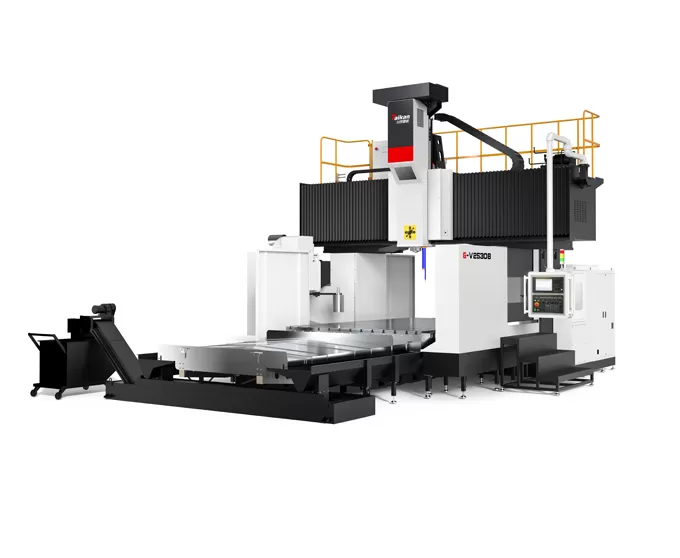
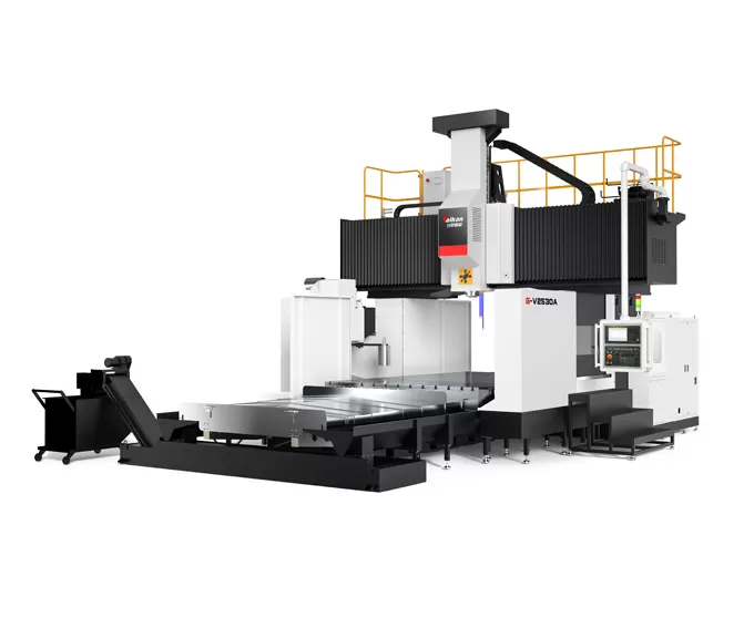
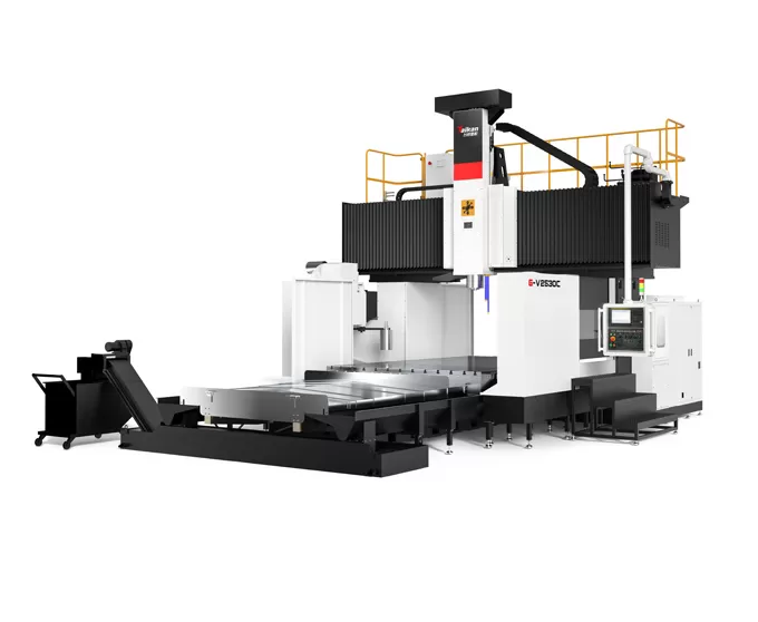
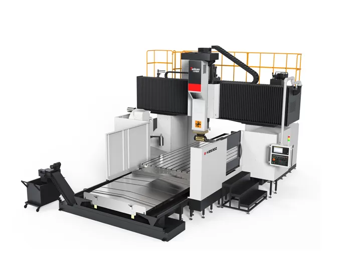
Gantry Machining Center
Machine Structure
The machine features a gantry frame fixed structure with a moving worktable.
High-Rigidity Beam: The beam adopts a rectangular large cross-section arch design. The height-to-width ratio is optimized through simulation analysis, significantly enhancing its bending and torsional resistance, ensuring precision stability.
Large Cross-Section Ram: The ram has a cross-sectional size of 420x420mm, supported by four linear guide rails in a semi-enclosed arrangement. This provides high-strength support with low friction resistance, ensuring zero creep at low speeds, minimal vibration, fast response, and excellent dynamic and static performance, low maintenance requirements, and long service life.
Multiple Support Table: The table is supported by multiple closely spaced slides, ensuring stable and reliable load-bearing performance with excellent precision retention.
Diverse Spindle Options
Various Drive Options
Configurable with belt drive, geared head, electric spindle, and automatic right-angle milling head.
Gear-driven Spindle
Features a BT50 interface with a maximum speed of 6000rpm and an output torque of up to 1331Nm. The gearbox and main motor are separated from the spindle, effectively minimizing accuracy issues caused by heat generation.
Motorized spindle
High-power, heavy-duty BT50-10000rpm electric spindle that delivers high torque, high speed, and low vibration, providing an exceptional machining experience.
Belt-driven Spindle
Utilizes a BT50-6000rpm high-speed spindle unit, offering efficient cutting performance.
Thermal Control
Standard with an oil cooling system to reduce spindle temperature, prolong bearing life, and minimize the impact of thermal deformation on machining accuracy.
Feed System
Three-Line Rails: All three axes (XYZ) use heavy-duty roller linear guide rails, which are easy to maintain, have low friction resistance, fast response from moving parts, zero creep at low speeds, and excellent dynamic and static performance.
Belt Drive: The XY-axis motors use belt reduction to increase transmission torque, reduce load inertia, improve drive performance, and provide simple and cost-effective maintenance.
Gear Drive: The motor is reduced through a low-backlash reducer, increasing torque transmission. Combined with larger lead screws, this ensures fast drive speeds, stable performance, and high precision (X-axis ≥ 4200mm / Y-axis ≥ 3700mm).
Nitrogen Balancing: The Z-axis drive system uses a servo motor directly coupled to a ball screw, with a dual-cylinder balancing system on both sides of the ram to ensure smooth reversal of Z-axis feed and fast dynamic response.
Thermal Compensation: The ball screw features a pre-tensioned structure at both ends, effectively eliminating precision loss caused by thermal expansion.
Chip Removal and Coolant Tank
Spiral Chip Conveyor: One set on each side of the worktable, with a 120mm screw diameter and large square steel cross-section, quickly expelling chips outside the machine.
Chain-type Chip Elevating Conveyor: Located at the machine's end, with a 45-degree incline, wider chain plate, and sawtooth scraper bars, quickly collecting chips into the small chip conveyor.
Small Chip Conveyor: Collects and transports chips.
Coolant Tank: Multi-layer filtration system to filter impurities and ensure smooth machining.


The machine series is mainly used for high-speed and high-precision machining of parts in industries such as automotive components, molds, construction machinery, valves, rail transit, energy, agricultural machinery, and coal mining machinery.
Item | Unit | G-V2530B | G-V2540B | G-V2550B | G-V2560B | G-V2530C | G-V2540C | G-V2550C | G-V2560C | ||
Travel | X-axis travel | mm | 3200 | 4200 | 5200 | 6200 | 3200 | 4200 | 5200 | 6200 | |
Y-axis travel | mm | 3200 | 3200 | ||||||||
Z-axis travel | mm | 1000(Opt. 1250) | 1000(Opt. 1250) | ||||||||
Distance from spindle end to table | mm | 250~1250(Opt. 250~1500) | 100~1100(Opt. 100~1350) | ||||||||
Effective gantry width | mm | 2980 | 2980 | ||||||||
Table | Table size (L×W) | mm | 2500*3000 | 2500*4000 | 2500*5000 | 2500*6000 | 2500*3000 | 2500*4000 | 2500*5000 | 2500*6000 | |
Max. load | kg | 18000 | 22000 | 25000 | 28000 | 18000 | 22000 | 25000 | 28000 | ||
T-slot (Width×Pitch×Qty) | mm | 28*200*13(160 pitch between bilateral T-slot rows) | 28*200*13(160 pitch between bilateral T-slot rows) | ||||||||
Spindle | Drive type | / | Gear drive(Opt. Belt drive) | Motorized spindle | |||||||
Max. spindle speed | r/min | 6000 | 10000(Opt. 15000, 18000) | ||||||||
Spindle power (Rated/Peak) | kW | 22/35 | 26/45 | ||||||||
Torque output (Rated/Peak) | N.m | 790/1258 | 305/623 | ||||||||
Ram section (Square ram) | 420*420(Opt. Z-Axis box ways 400*400, 450*450) | 420*420 | |||||||||
Spindle taper | / | BT50 | BT50(Opt. BBT40, HSK-A63) | ||||||||
ATC (Opt.) | Number of tools | T | 24(40) | 24(40) | |||||||
Max. tool dia. (Full/Adjacent) | mm | φ110/φ200 | φ110/φ200 | ||||||||
Max. tool length | mm | 350 | 350 | ||||||||
Max. tool weight | kg | 18 | 18 | ||||||||
Speed | Feed rate range (Cutting) | m/min | 8/8/8 | 8/8/8 | 6/6/6 | 6/6/6 | 8/8/8 | 8/8/8 | 6/6/6 | 6/6/6 | |
Rapid traverse speed (X/Y/Z-axis) | m/min | 12/15/15 | 10/15/15 | 10/15/15 | 10/15/15 | 12/15/15 | 10/15/15 | 10/15/15 | 10/15/15 | ||
Accuracy | Positioning accuracy | X | mm | 0.027/0.023 | 0.032/0.028 | 0.036/0.032 | 0.041/0.037 | 0.027/0.023 | 0.032/0.028 | 0.036/0.032 | 0.041/0.037 |
Y | mm | 0.027/0.023 | 0.027/0.023 | ||||||||
Z | mm | 0.018/0.014 | 0.018/0.014 | ||||||||
Repeatability | X | mm | 0.017/0.015 | 0.02/0.018 | 0.023/0.021 | 0.025/0.023 | 0.017/0.015 | 0.02/0.018 | 0.023/0.021 | 0.025/0.023 | |
Y | mm | 0.017/0.015 | 0.017/0.015 | ||||||||
Z | mm | 0.012/0.011 | 0.012/0.011 | ||||||||
Others | Z-axis counterweight | / | Hydraulic + nitrogen balance | Hydraulic + nitrogen balance | |||||||
CNC system | / | FANUC 0I-MF PLUS (Opt. Siemens 828D) | FANUC 0I-MF PLUS (Opt. Siemens 828D) | ||||||||
Air supply | Flow | L/min | 300 | 300 | |||||||
Pressure | MPa | 0.6~0.8 | 0.6~0.8 | ||||||||
Total electrical capacity | kVA | 65 | 65 | ||||||||
Coolant tank capacity | L | 700 | 700 | ||||||||
Machine size | Length | mm | 8015 | 10020 | 12164 | 14645 | 8015 | 10020 | 12164 | 14645 | |
Width | mm | 6634 | 6634 | ||||||||
Height | mm | 5200(5900 when Z axis is optional) | 5200(5900 when Z axis is optional) | ||||||||
Machine Enclosure | - | Semi-surrounding sheet metal (work area only) | Semi-surrounding sheet metal (work area only) | ||||||||
Notes:
1:G-V2530A、G-V2540A、G-V2550A、G-V2560A – Optional 6000 RPM belt-driven spindle, output torque 186/297 N·m.
2:G-V2530Z、G-V2540Z、G-V2550Z、G-V2560Z – Optional fully automatic right-angle milling head, with a Y-axis travel of 3700 mm.
3:G-R2530B、G-R2540B、G-R2550B、G-R2560B – Optional Z-axis square ram (Z = 1000 mm, machine height 5600 mm; Z = 1250 mm, machine height 6300 mm).
4:G-R2530Z、G-R2540Z、G-R2550Z、G-R2560Z – Optional Z-axis square ram + automatic right-angle milling head (Y-axis travel 3700 mm; Z = 1000 mm, machine height 5600 mm; Z = 1250 mm, machine height 6300 mm).
The information on this page is for reference only. Specifications and details may change due to product upgrades or improvements. For more information, please contact us.

FANUC

Siemens

Mitsubishi

Apr 11 2025

Apr 01 2025


